Decoding the DCF77 signal with Blech
What is DCF77?
DCF77 is a longwave radio signal which is widely used in Germany for time synchronization of clocks and watches. The signal transmitter is located in Mainflingen (Germany) and controlled by the Physikalisch-Technische Bundesanstalt (PTB).
Information about the current time and date are modulated in a binary fashion onto a 77.5kHz radio carrier signal. On each second a so called second mark is transmitted by reducing the carrier power for a certain amount of time. The duration of the reduction encodes either a binary zero (100ms) or a binary one (200ms). After a complete time code – a sequence of 59 bits – the process is repeated every full minute. For the 60th second there is no level change. This gap aids as a synchronization mark for indicating the end of the current time code.
Please refer to the homepage of the PTB for further details about the technical setup and the time code of DCF77.
Application example: DCF77 decoder
Our goal is to implement a simple DCF77 decoder based on a STM32F4DISCOVERY board. For the user interface we use the on-board LEDs and push button. The application shall behave as follows:
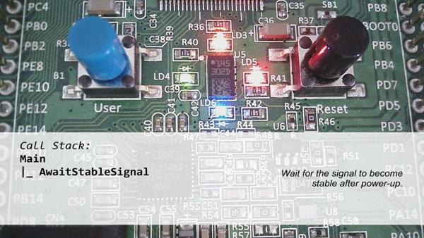
- After power-up the application waits until the DCF77 signal is stable. During this time all LEDs are turned on.
- When the signal ist stable the decoding process starts automatically. All LEDs are turned off.
- While the decoding is running the blue LED visualizes the current level of the time signal. If the signal is
HIGHthe LED is turned off and vice versa. This means whenever a new second mark has been received the LED lights up for 100 or 200 milliseconds. - As soon as the synchronization mark has been captured the orange LED is turned on. This shows that capturing the time code is now actually in progress.
- Finally, if the decoding has been successfully completed the green LED lights up while the orange one goes off. In case of an error the decoding stops immediately and the red LED is turned on.
- Irrespective of success or error the user has to press the button in order to start a new decoding process.
In order to receive the DCF77 time signal an additional receiver module – similar to this one – is required. It basically receives and transforms the radio signal into a digital low-voltage TTL signal used as input for the microcontroller. The complete hardware setup is shown below.
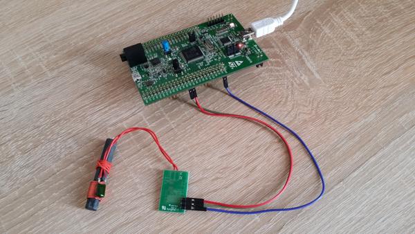
Hardware setup of the DCF77 decoder: Discovery board (top) and RF receiver module with antenna (bottom).
Jumper wires are used to connect the receiver module to the discovery board as follows:
| # | Pin (RF Module) | Pin (Discovery Board) | Description | Wire |
|---|---|---|---|---|
| 1 | - | GND | Ground | blue |
| 2 | Signal | PB7 | DCF77 Signal | green |
| 3 | + | VDD | Supply Voltage | red |
Note that PB7 is a simple GPIO configured as digital input. By connecting an oscilloscope to PB7 we check that the receiver module is working as expected. The scope visualizes how the DCF77 bits literally “fly” – so to speak – into the microcontroller:
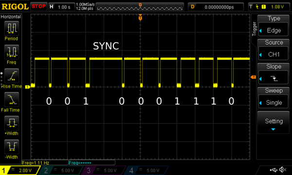
Oszilloscope capture of the DCF77 time signal on GPIO PB7.
We can also see the synchronization mark (SYNC) in which the 60th low pulse is omitted. This is the delimiter between the current bit sequence and the following. Finally, the discovery board communicates via USB with the software IDE
on the development machine for code flashing and debugging.
Implementation outline
In this section we outline the decoder implementation, thereby focusing on the Blech application part and its integration into the C execution environment. The complete source code project can be found here . Two files are of particular interest:
- main.c – the main file of the C execution environment.
- control.blc – the Blech application part.
Interface between C and Blech
The Blech application part is responsible for the following concerns:
- Decoding the DCF77 signal – requires the time signal level as input from C to Blech.
- Controlling the LEDs – requires the state of the blue, orange, green and red LED as output from Blech to C.
- Reacting to button presses – requires the state of the user button as input from C to Blech.
The corresponding signature of the Blech entry point activity looks like this:
|
|
Note that LedStates is a user-defined structure in Blech which contains the state information of the four LEDs. This is done to make the interface less verbose, thereby improving the readability.
Execution scheme and integration of Blech
The execution progress of a Blech program advances based on ticks. A tick can be any sporadic or periodic event- or time-based trigger provided by the underlying hard- and software platform. For decoding DCF77 it is a common approach to periodically sample the time signal and measure the duration of the level changes. This means that the entire decoding logic is purely time-driven based on a cyclic timer tick.
We follow this approach and execute the Blech application part every 10 milliseconds. This leads to a sample rate of 100Hz which is sufficiently fast in order to distinguish between a binary zero, a binary one and the synchronization mark. For the periodic execution, we take advantage of a simple delay function (HAL_Delay) provided by the microcontroller’s driver library. An outline of main.c is shown below.
|
|
Basically, the main function initializes the system and the Blech execution context. It performs the very first reaction in Blech – the boot reaction – and enters the infinite loop. Inside the loop, we repeatedly wait for the next tick to occur and perform the next reaction in Blech accordingly. The actual call of blc_blech_control_tick is wrapped in perform_reaction in order to encapsulate all the required steps for reading the Blech inputs and writing the Blech outputs.
Note
In this application, the Blech part is entirely time-triggered. Allawait statements react in response to the periodic 10 milliseconds tick. Thus, calling await true – which means “await the next Blech tick” – will suspend the running trail for the next 10 milliseconds. This allows to implement a time-driven counter for measuring durations, e.g. of the signal level changes (see here
).
Keep in mind that calling HAL_Delay is generally not a good solution with respect to efficiency. Internally, this function actively polls a variable which gets updated by the system tick timer. This means that the CPU is continously running at full speed and the main thread is blocked for anything else. A better approach would be to switch the microcontroller into sleep mode and implement a wakeup strategy based on interrupts for each tick. We are going to show this in another blog post. In this example, however, we follow the simple delay approach for the sake of simplicity.
Hierarchical software structure
The entire complexity of the example application is broken down into seven activites – the reactive code abstraction entities in Blech – as follows:
Main– This is the entry point and top level of the Blech program. It defines the interface between Blech and C (see here ) and describes the application behaviour on a high abstraction level.AwaitStableSignal– This waits for the DCF77 time signal to become stable. When the system is powered up the RF receiver module needs some time to stabilize its oscillator and supply voltage. During this time the signal is not reliable.Visualize– This visualizes the DCF77 signal level using the blue LED.Decode– This actually decodes the DCF77 time signal.CaptureTimeInfo– This captures and decodes one time code, means one sequence of 59 bits which is transmitted every minute.CaptureBit– This captures one second mark and evaluates it to either a binary zero or a binary one.CaptureSync– This captures the synchronization mark.
The following graph depicts the hierarchical decomposition and call dependency of the above activities. In particular, it shows that the DCF77 decoding relies on capturing the time code which, in its turn, relies on capturing the synchronization mark and the bits.
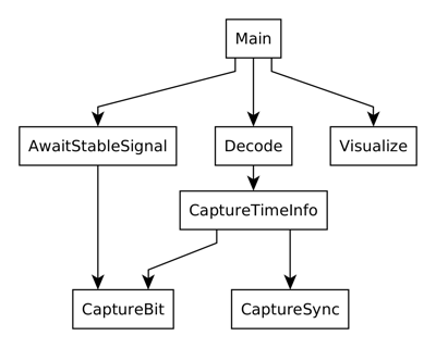
Hierarchical call structure of activities.
Note how easy it is to reuse the same piece of reactive code for different concerns in Blech – CaptureBit is used in AwaitStableSignal and CaptureTimeInfo likewise. In the former, we repeatedly run CaptureBit until three consecutive bits have been successfully captured. Only then we consider the time signal to be stable.
The application’s top-level
We dig into the implementation starting at the top level. Inside the Main activity, the program first awaits a stable DCF77 signal by running AwaitStableSignal. This suspends the control flow until the signal is reliable. A function call is used before to turn on all LEDs.
After that, the infinite repeat loop is entered and all LEDs are turned off. By taking advantage of cobegin, the main application trail is split into two concurrent trails. While the first one runs Decode for performing the DCF77 decoding, the second one executes Visualize in order to concurrently reflect the time signal level on the blue LED. Note that the second trail is marked as weak. This means that, as soon as the first trail terminates, the second trail will be aborted – both trails rejoin their control paths and continue as one. By this, it is pretty easy to describe that visualizing the signal level shall be done only while the decoding is running.
Note
Due to the synchronous computation model, abortion of trails is done only at the end of the current reaction when all trails have finished their job and are waiting for the next tick. Thus, trails are particularly not interrupted at an arbitrary code location because this would lead to non-deterministic runtime behaviour!
|
|
After decoding has been finished, all LEDs are turned off again and we check for success or error. On success, the green LED is turned on while on error the red LED is turned on. Finally, the Blech program suspends until the push button is pressed by the user. Once this is done the whole process restarts.
Note
To keep the example simple, the button state is provided as-is to the Blech program. This means we just pass the current value of the corresponding GPIO input register. Usually, however, it is common practice to apply a filter approach in software in order to suppress bouncing . In this blog post we are going to show how this can be done in Blech.Visualizing the DCF77 signal
Reflecting the time signal level on the LED is a pretty simple task in Blech. We establish an infinite loop which alternates between the signal levels. First, it awaits the high level for switching off the LED. Second, it awaits the low level for switching on the same LED. Third, the whole process repeats – that’s it.
|
|
Note that Visualize does not even have to know which of the four LEDs it is actually turning on and off. There is no hardware dependency and all the required logic is encapsulated in an activity. Thus, we could easily select another LED or execute multiple instances of Visualize concurrently in order to show the signal level on several LEDs at the same time.
Capturing the synchronization mark and the bits
For this functionality, we take advantage of the fact that the entire Blech application is purely time-triggered by the 10 milliseconds tick (see here
). Based on that, we establish a time-based counter len which measures the duration of the signal’s HIGH level. Therefore, len is incremented on each (10 milliseconds) tick using await true in a loop. Once that counter has reached the required value (> 1200ms) we detect the synchronization mark and exit the loop.
If the signal level goes LOW during the measurement the process has to be resetted. For this, we use the when ... reset block in Blech which causes the contained code to restart from the first line if the given condition is met. So in this case the code will jump back to var len: nat16 = 0 as soon as the level drops.
|
|
The implementation of CaptureBit basically follows the same approach. It uses a time-driven counter for measuring the duration of the LOW level instead. For this reason, we do not exemplify it in more detail here.
Capture and decode the time information
Implementing the time information capture based on CaptureSync and CaptureBit becomes a trivial task. First, we capture the synchronization mark. Before and after that we turn off and on the associated LED (orange) respectively. Second, we enter the while loop in which we collect the 59 time code bits by repeatedly calling CaptureBit. Each successfully received bit is passed to processBit in order to update the gathered time information in ti. This means that decoding the DCF77 signal actually happens bit-wise on-the-fly. Finally, CaptureTimeInfo terminates, thereby returning the success status and the decoded time information to the caller.
|
|
The job of Decode is to retrieve two consecutive time codes (tmp and ti) and apply a simple validity check by comparing them. A common approach is to check whether the second timestamp (ti) is exactly one minute ahead of the first one (tmp). If that is the case the second one is considered valid and returned to the caller – the decoding is done.
|
|
Conclusion
The following video shows the DCF77 decoder in action. In focus are the four color LEDs and the user button on the left side. Watch the video to get in impression about how above Blech activities control the runtime behaviour.
Video: The DCF77 decoder in action.
Above implementation outline shows that implementing DCF77 decoding is a straightforward job in Blech. The combination of the synchronous execution model and activities allows to divide the entire decoding complexity into smaller parts that are easier to program, comprehend and maintain. In particular, it is possible to compose these reactive functionalities in a hierarchical top-down fashion. All concurrent behaviour is deterministic by design and does not require any mutexing.