Push button handling
Application example: Push button handling
In this example three push buttons, TOP, CENTER and BOTTOM, are connected to our embedded system for user input. Like in our previous blog post
our hardware setup is based on a STM32F4DISCOVERY
board. The latter has four color LEDs, red, blue, green and orange, which we are going to use for showing the button states.
Additionally, we connect a small breadboard with three general purpose push buttons. All buttons share a common electrical ground on the left-hand side of the breadboard. On the right-hand side, there is an individual signal wire for each button which is connected to a dedicated GPIO of the discovery board. The pull-up resistors of these GPIOs are active.
Finally, we connect two probes of an oscilloscope. Channel 1 (CH1) connects to a debug pin which is set to HIGH while Blech code is executed. Channel 4 (CH4) connects to the output signal of BOTTOM for demonstration purpose. The complete setup is depicted below:
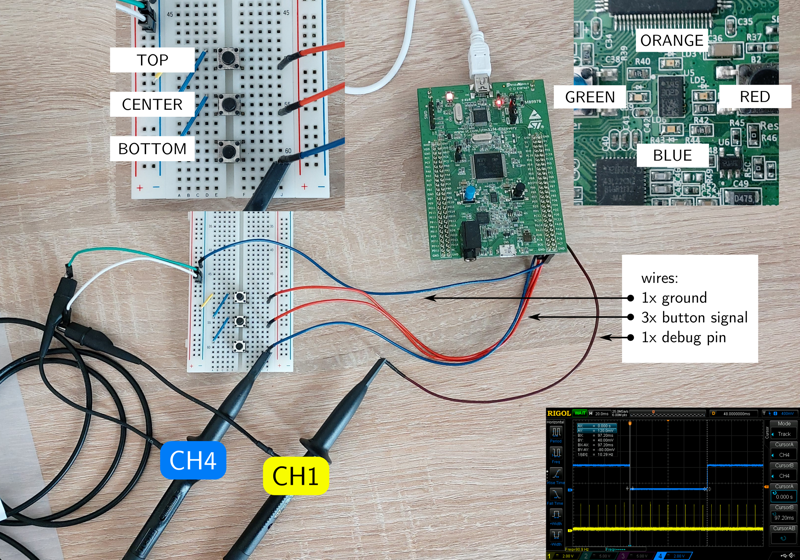
Hardware setup for the push button handling example.
By default, the electrical contacts of the push buttons are open. Thus, the pull-ups on the discovery board will tie the button output signals to the supply voltage (+3.3V) while they are not pressed. If a button gets pressed it pulls the output signal to ground (0V). This means that, physically speaking, the buttons are active-low – the corresponding GPIO input register on the discovery board will be 0 if the button is pressed, 1 if it is not pressed.
In order to make our Blech code more readable, we invert the physical signal level into a logical signal level as follows:
| Button state | Physical signal level | Logical signal level |
|---|---|---|
| not pressed | +3.3V (HIGH) |
false (LOW) |
| pressed | +0.0V (LOW) |
true (HIGH) |
When passing the GPIO input register values from C to Blech 0 is changed to 1 and vice versa. Then, in Blech, the button signal states are mapped to bool variables. They will be true when the corresponding button is pressed, false if it is not pressed, thereby making the buttons active-high in software.
The goal of this application example is to show how we can handle button inputs in Blech. This involves filtering the button signals , detecting a button event and finally properly react to that. In the following sections we examine this in more detail.
The complete project source code is available here on Github.
Interlude: Physical time
In practically all embedded applications we have to describe temporal behaviour in our software – at least to a certain extent. The different use cases typically fall into two categories:
-
Delays: Sometimes the embedded system is much faster than its (physical) environment. In order to account for this speed difference, an artificial slowdown of the embedded software is required. This means that we deliberately suspend the code execution until a certain amount of time – the delay time – has been passed.
-
Timeouts: Sometimes we just need to know whether a certain event, or sequence of events, has happend before or after a certain amount of time – the timeout time – has been elapsed. Depending on that the embedded software is going to behave differently.
Both types require to express physical time in our code. For this, we establish the same execution scheme for Blech as described in this
blog post. That is, the entire Blech code is purely time-driven based on a periodic system tick. Based on this, we can easily implement a small helper activity AwaitMsec in Blech for suspending the program for an arbitrary number of milliseconds. The maximal resolution is given by the period interval of the system tick which is set to 10 milliseconds in this example.
|
|
Depending on the given number of milliseconds to wait, AwaitMsec first determines the corresponding number of system ticks (line 4). Second, it awaits the relevant number in a repeat loop (lines 5 – 8). Calling run AwaitMsec(50) causes the running trail to suspend for five system ticks for example. With this approach it is straight forward to implement delays
and timeouts
in Blech.
Delay
For realizing a delay of 120 milliseconds between two function calls funcA() and funcB() for instance we can directly use AwaitMsec as follows:
|
|
This code snippet first executes function funcA, then suspends the running trail for 120 milliseconds (= 12 system ticks) and finally calls function funcB.
Timeout
For applying a timeout of 120 milliseconds onto an activity SomeActivity for instance we can use AwaitMsec in a concurrent trail as follows:
|
|
In this solution, we first declare two variables, done and timeout, which indicate whether or not SomeActivity has been completed in time (lines 1 – 2). Then, in the cobegin, we execute two concurrent trails in which the first one (lines 4 – 5) runs the actualy activity while the second one (lines 7 – 8) is responsible for checking the timeout.
Both trails are weak so that they can abort each other depending on which event – the completion of the activity or the timeout expiry – happens first. Once the trails rejoin (line 10) we can use done and timeout to precisely distinguish the different scenarios as shown below:
| Scenario | done |
timeout |
Result | Note |
|---|---|---|---|---|
false |
false |
- | done or timeout are true. |
|
| 2 | false |
true |
timeout | SomeActivity has not terminated in time. |
| 3 | true |
false |
success | SomeActivity has terminated in time. |
| 4 | true |
true |
? | SomeActivity has terminated in the same reaction in which the timeout time has elapsed. This means that, according to the synchronous model of computation, both events have happened simultaneously. In this case it is up to the application logic to treat this as success, timeout or maybe something else. |
Note
Again, note how easy it is in Blech to use the same piece of reactive code (AwaitMsec) for different concerns (delays and timeouts) likewise.
Signal filter
In order to provide a good user experience we want to detect only notable level changes of the button signals. Glitches and high frequent noise that might be caused by bouncing for instance shall be filtered out before we actually evaluate and consider the current button state in our software. For this purpose, we implement three dedicated activities, starting from bottom to top:
Await a stable level
First, AwaitStableLevel is responsible for checking the stability of the button output signal. Input lvl is the signal level that shall be awaited until it is stable. Input btnRaw is the raw button signal as retrieved from the GPIO. For example, run AwaitStableLevel(false, btns.top) means we want to suspend execution until the logic level of button TOP is reliably LOW.
|
|
In order to decide whether lvl is stable or not this activity establishes a very simple voting strategy. Every 10 milliseconds (line 6) it checks the current state of the button signal. If it is equal to lvl this is interpreted as match whereby vote gets incremented (lines 7 – 8). If it is not equal this is interpreted as no match whereby vote gets decremented (lines 9 – 10).
As soon as five consecutive matches have been detected the signal is considered stable – the repeat loop exits (line 12) and AwaitStableLevel returns. Its runtime behaviour is illustrated in the oscilloscope capture below:
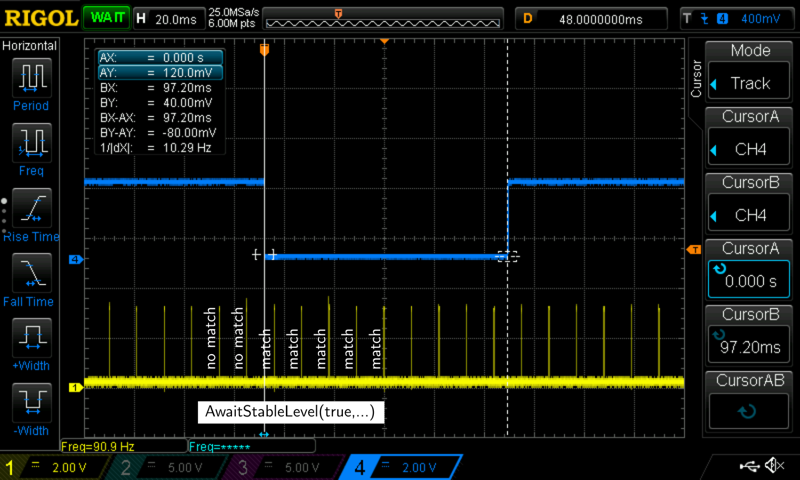
Oszilloscope capture of button sampling. CH1 shows the execution of the Blech code. Each peak is one run of the Blech tick function and hence constitutes one reaction respectively computation step according to the synchronous model of computation. CH4 is the raw button signal.
Remember that CH1 shows the debug pin signal which is pulled high whenever Blech code is running. Each yellow peak is one run of the Blech tick function and hence constitutes one reaction respectively computation step according to the synchronous model of computation. In particular, it is the run AwaitMsec(10) in AwaitStableLevel that causes our Blech code to get executed periodically, thereby determining the sampling rate of the button signals. The scope capture verifies that above repeat loop actually checks the current state of the button signal exactly every 10 milliseconds – the correct temporal behaviour as expressed in our Blech code.
At the bottom of the scope capture you can see an exemplary run of run AwaitStableLevel(true, btnsRaw.bottom). Remember that CH4 shows the physical output signal of BOTTOM with inverted logic – we await true in our software, means 0V in hardware! As a consequence, the first two samples lead to a no match while the next five samples are matches. As soon as the fifth match has been captured the activity returns.
Filter a single button signal
Second, FilterSignal is responsible for filtering the signal of a single button. Input btnRaw is a raw button signal, output btnis the filtered one. Based on a simple repeat loop (lines 2 – 10), this activity continuously alternates btn between the two possible button states false (not pressed, line 3) and true (pressed, line 7):
|
|
A transition from false to true is only done once the raw signal btnRaw is true and considered stable. The same applies vice versa for the transition from true to false. Checking the signal stability is done by AwaitStableLevel as shown above.
Note
Note thatFilterSignal is completely hardware-independent. At development time, it does not need to know which hardware signal it is actually working on. It just implements the algorithm used for filtering a signal, irrespective of whether this signal belongs to button TOP, CENTER or BOTTOM – it does not even have to be a button signal at all. This allows to reuse and instantiate the same reactive code for different hardware entities. In conventional approaches, this is usually hard to achieve.
Filter all button signals
Third, FilterButtons is responsible for filtering the signal of all buttons. It is the top level activity with respect to filtering. Input btnsRaw are the raw button signals as retrieved from the GPIOs, output btns are the filtered button signals. Internally, this activity runs a dedicated filter activity for each individual button – TOP, CENTER and BOTTOM. These activities are concurrently composed in the same cobegin block. So FilterButtons is basically a wrapper for comfortably running three instances of FilterSignal concurrently.
|
|
Later, in the Main activity of our Blech program, we can concurrently run FilterButtons with respect to the remaining code (see line 7 below). In each reaction, the filtered button signals btns are automatically updated (written) by FilterButtons in the first trail and can be used (read) by other activities in concurrent trails. Activity Visualize, for example, uses the filtered button signals in order to reflect the current button states on the color LEDs (line 10 below).
|
|
Event detection and reaction
Above sections show how raw button signals can be filtered in Blech. Now, we want to use the filtered signals btns for detecting button events and performing a corresponding reaction. For this purpose, we have implemented some example activities that show different application use cases.
In each example, we want to detect a certain type of button event and, as an example of an arbitrary event reaction, turn on the red LED of the discovery board. After a certain release condition is met, the red LED is turned off again.
Note
At this point, the example activities do not have to care about signal glichtes, noise, bouncing or filtering in any way. In each reaction, they can fully rely on the output of the “upstream” filter activities – so to speak – and just focus on their own business. This means that both concerns, signal filtering and signal evaluation, are completely separated in our Blech program.Example 1: Press button for at least x seconds
In this example, the LED shall light up once CENTER has been pressed for at least two seconds. It shall stay on as long as the button is pressed and go off once it has been released.
|
|
The first step is to wait until the button is pressed (line 3). After that, we use AwaitMsec in order to wait until two seconds have elapsed. If the button should be released meanwhile we automatically restart the process by taking advantage of Blech’s when ... reset block (line 2).
Once control flow reaches line 6, we know that CENTER has been pressed for two seconds and hence turn on the LED. Finally, we wait for the button to be released (line 7) and turn off the LED (line 8) as a consequence.
Example 2: Two buttons have to be pressed
In this example, the LED shall light up once TOP and BOTTOM are pressed. After that, it shall be turned off as soon as both buttons have been released.
|
|
This implementation is trivial in Blech. In line 2, we wait until both buttons are pressed, then turn on the LED (line 3). Subsequently, we wait until none of the buttons are pressed (line 4) and finally turn off the LED (line 5).
The simplicity of this piece of code is caused by the fact that we do not care about timing in this example. No matter when or how long the buttons are pressed, we only have to check whether their is at least one reaction in which both button signals are true. For detecting a real-world double button press a more sophisticated approach is usually required. We demonstrate this in Example 3
.
Example 3: Double button press
In this example, the LED shall light up if a double press of TOP and BOTTOM is detected. After that, it shall be turned off once both buttons have been released. In contrast to Example 2
, here it is important that both buttons are pressed within a certain amount of time. For example, we only accept a double press if the time gap between the two button presses is one second at most.
|
|
The repeat loop in line 4 is used to check for the double press. First, we await the idle state – both buttons are not pressed. Second, we wait until at least one of the buttons has been pressed (line 7). Subsequently, we handle the different, possible scenarios:
-
Line 9: Both buttons are pressed. In this case, the double press is already detected. However, this case might be quite rare since it is difficult to perfectly push down both buttons at the same time so that they will be pressed in the same reaction.
-
Line 12:
TOPis pressed,BOTTOMnot yet. In this case, we useAwaitOtherButtonin order to awaitBOTTOMto get pressed within the accepted delay of one second. On successrepeatexits. The implementation ofAwaitOtherButtonis shown below. -
Line 15: Same as in (2) but
TOPandBOTTOMare exchanged.
In any case, once the repeat loop has been left, we know that a valid double press has been detected and hence turn on the LED. Finally, we wait until both buttons have been release and turn off the LED.
The helper activity AwaitOtherButton demonstrates timeout handling
in Blech. We want to know if the second button btn2 is pressed within the given amount of milliseconds (msec) and while the first button btn1 is still pressed. So there are actually two conditions to be checked – the timeout and the current state of btn1.
|
|
For the first condition, we basically apply the same approach as described above
using a concurrent composition (line 4). Note that both trails are weak so that they can abort each other. Result variable success is only set to true (line 6) if the button press happens before the timeout. If there is a timeout – means run AwaitMsec(msec) returns – the cobegin rejoins and success is still false.
For the second condition, we surround the concurrent composition with a when ... abort block that monitors the state of btn1. Once it is not pressed anymore the entire block aborts, again leaving success untouched (false). Finally, AwaitOtherButton returns the result which is then used by the caller to decide whether the second button has been pressed in time or not.
Example 4: Measure the button press duration
In this example, the LED shall light up if CENTER has been pressed between one and two seconds. After that, the LED shall be turned off once TOP has been pressed.
|
|
In contrast to the other examples above, we actually measure the button press duration here. For this, we use two repeat loops.
The inner loop (lines 6 – 9) is used to measure the duration of the current button press which has been detected in line 4. It repeatedly awaits 10 milliseconds and increments the counter i for measuring the duration. The surrounding when ... abort automatically exits the inner loop as soon as the button is not pressed anymore. The outer loop (lines 3 – 11) is used to check whether i is in the desired time interval or not. If not, the entire process repeats.
Once we hit line 13 we know that the current button press matches the given time interval. Consequently, the LED is switched on. Finally, we wait until TOP has been pressed in order to turn off the LED again.
Conclusion
The below diagram depicts the architecture of the Blech program as function blocks. Moving from left to right, the three raw button signals btnsRaw are handed over from the C environment to the Main activity of Blech. At this point, they are forwared to the filter activity FilterButtons which, in its turn, passes each raw signal to a dedicated instance of FilterSignal likewise. The latter internally uses AwaitStableLevel for the actual filter process. Finally, the filtered signals btns are provided to the remaining, concurrent Blech code, e.g. Visualize for controlling the color LEDs or one of our Example activities as described above.
Note that FilterButtons and FilterSignal will never terminate. They are designed to run infinitely throughout the entire livetime of the Blech program. In contrast, AwaitStableLevel is called several times during runtime and terminates whenever the desired signal level is stable.

Architecture of the Blech program as function blocks.
Last but not least, the block diagram shows that, on the top level, our Blech program behaves like a reactive control block. It receives the raw button signals as inputs, processes them based on events (and time) and finally outputs the corresponding control signals for the color LEDs.